POWMAN P-State and Low-Power Modes on Raspberry Pi Pico 2 (RP2350) with Rust
Explore the RP2350's POWMAN P-state and low-power features with Embedded Rust. Learn how to use the AON Timer and RP2350 PAC to put the Pico 2 into a deep low-power state and wake it up. I was working on a hobby Embedded Rust project where the MCU needs to wake up every few hours, do some work, and then go back to sleep. The project will run on a battery, so I want to reduce power consumption as much as possible. Some STM32 microcontrollers have nice low-power modes, but I have already bought quite a lot of hardware recently and didn’t want to buy another board just for this (at least for now 😉). I already had a Pico 2 (RP2350), so I wanted to utilize that instead. The Pico 2 has some interesting low-power features that the older RP2040 does not have. The RP2350 has POWMAN, which can significantly reduce power consumption. I wanted to make use of that instead, so I started exploring and researching how it works and how I can use it with Embedded Rust. In order to achieve low power consumption, a microcontroller usually has features to put components that are not being used into a low-power state. Even the processors can be put to sleep when they have nothing to do. The original Pico (RP2040) has two sleep modes, known as The Pico 2 (RP2350) adds a third mode called P-state, which can switch off power domains instead of just stopping the processor or clocks. A power domain is basically a section of a chip that can be independently powered on or off. The RP2350’s core logic is divided into five power domains: You can find more details in the Power Management section. The RP2350 has a dedicated hardware block called POWMAN (Power Manager) that controls these power domains. When you switch off a power domain, its state is lost. So if you want to keep some data, you need to keep it in a powered domain. The Pico SDK has a nice table that shows the power consumption of the RP2040 and RP2350 in different modes. It shows how much lower the power consumption can be with P-state compared to SLEEP and DORMANT modes. This is just a simplified version of that table. For my hobby project, I don’t need to retain any RAM data or continue from where I left off. A fresh run every time the Pico wakes up is enough for me. So I can turn off as much of the chip as possible while it is sleeping, as I don’t need to keep its previous state. The datasheet uses the notation I don’t want to go into all the details here. You can refer to the datasheet if you want to understand the power states in depth. I will just give a brief explanation of how the notation works. Let’s see a few example states: In this table, In normal operation, the RP2350 is in If we only want to turn off the SWCORE domain, it is represented as I want to turn off SWCORE, XIP, SRAM0, and SRAM1. So, the memory part becomes Once we power down the components, including the CPU, we need a way to wake them up. The one domain that always runs is AON (Always On), as the name suggests. We will use the AON Timer to trigger an alarm after a specified amount of time. We can use this alarm to wake the Pico from its low-power state. Enough with the theory, let’s get into the coding part. I will use the template I created for the “impl Rust for RP2350” book and work on top of it. I won’t cover the basic boilerplate code here. The overall flow: I needed a simple indication that the program is working. So, I will blink the onboard LED whenever the MCU boots. The LED turns on when the program starts and stays on for one second before turning off. Since the Pico boots again after waking from P-state, the LED will turn on again when the chip wakes. First, we need to bind the interrupt used by the AON Timer: Next, we configure the AON Timer to use the low-power oscillator at 32 kHz: And then start the timer: Finally, we set an alarm for 10 seconds: The timer will continue running while the rest of the chip is in the low-power state. When the alarm is triggered, it will wake the Pico. Now, let’s create a function called I was looking for examples in Rust or C for achieving the P-state. I didn’t come across one for Rust. The Pico SDK has an example for low_power_pstate_timer.c, so I followed the function used by the example and tried to follow what the Pico SDK does as much as possible. The Pico SDK does some preparation before entering the P-state. One of them is disabling interrupts. I believe this is to prevent another interrupt from waking the processor while POWMAN is waiting to complete the transition. Currently, the HAL does not provide a high-level API for P-state. So, we will use the PAC. To apply the P-state, we need to modify the POWMAN registers. Let’s first get access to POWMAN: POWMAN registers are password protected and require a constant password ( Next, we tell POWMAN to ignore power requests from the debugger. We don’t want a connected debugger to prevent the chip from entering the requested power state. If you have never used register manipulation through a PAC before, this might look strange. Basically, we are modifying the Inside the closure, we call the Let’s unlock the voltage regulator so it can switch to the low-power state. We also need to configure how SRAM0 and SRAM1 should be powered when the chip wakes up. Since both SRAM domains are OFF in Now, we request the P-state we want by setting the After requesting the P-state, we will check whether POWMAN accepted the request: Let’s wait until POWMAN enters the Finally, we stop the processor and wait for the wake-up event: When we call this function, we will pass the value Here, the first bit of the P-state value represents Hurrah! We have written a complicated blinky program :P I have tested it by blinking the LED, and it is working. But, I am not sure whether it will introduce any side effects or how it will behave when I integrate it into a real project. If I run into any issues, I will update this. You can find the complete source code for this experiment on GitHub. Pico (RP2040) vs Pico 2 (RP2350) - Low Power Modes
SLEEP and DORMANT. In SLEEP mode, the processors go to sleep while the hardware needed for wake-up remains active and can generate an interrupt to wake the processors. In DORMANT mode, even the clocks and oscillators are stopped, allowing the RP2040 to reach a much lower-power state while retaining its system state so that execution can continue after waking.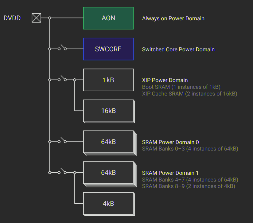
Mode Pico (RP2040) Pico 2 (RP2350) SLEEP 7.3 mA 5.9 mA DORMANT 0.95 mA 3.3 mA P-state, SRAM0 on - 0.25 mA P-state, XIP SRAM on - 0.22 mA P-state, all SRAM off - 0.18 mA Power State
Pc.m to describe a power state. Here, c indicates the state of the switched core (SWCORE) domain, while m is a 3-bit binary representation of the memory power domains in the order XIP, SRAM0, SRAM1.Power State SWCORE XIP SRAM0 SRAM1 P0.00 0 0 0 P1.01 0 0 0 P0.20 0 1 0 0 means ON and 1 means OFF.P0.0, which means all these power domains are ON.P1.0. If we want to turn off only SRAM0, the memory part becomes 010 in binary. 010 is 2 in decimal, so the power state is represented as P0.2.111 in binary, which is 7 in decimal, so we get P1.7. How Do We Wake Up?
Coding
Good Old Blinky
let mut led = Output::new(p.PIN_25, Level::High);
Timer::after_secs(1).await;
led.set_low(); Setting Up the AON Timer
bind_interrupts!(struct Irqs {
    POWMAN_IRQ_TIMER => embassy_rp::aon_timer::InterruptHandler;
});let config = aon_timer::Config {
clock_source: ClockSource::Lposc,
clock_freq_khz: 32,
alarm_wake_mode: AlarmWakeMode::DormantOnly,
};
let mut aon = AonTimer::new(p.POWMAN, Irqs, config);aon.start();aon.set_alarm_after(Duration::from_secs(10)).unwrap(); Entering a Power State
enter_pstate() that accepts the P-state as a u8. The P-state only uses 4 bits and ignores the rest. The function will be a diverging function because it never returns, so we mark its return type as !.cortex_m::interrupt::disable();let powman = pac::POWMAN;0x5AFE) to be written to the top 16 bits to enable the write operation. This helps prevent accidental writes to these registers.const POWMAN_PASSWORD: u32 = 0x5AFE << 16;pac::POWMAN.dbg_pwrcfg().modify(|w| {
w.set_ignore(true);
w.0 |= POWMAN_PASSWORD;
});DBG_PWRCFG register, which we access through the dbg_pwrcfg() function. The modify() function accepts a closure that can change the register value. Inside the closure, we modify the bits we are interested in. The register is written only after the closure completes.set_ignore() function with true, which sets the IGNORE bit. Then, as we mentioned earlier, we need to include the POWMAN password in the top 16 bits to authorize the write.powman.vreg_ctrl().modify(|w| {
w.set_unlock(true);
w.0 |= POWMAN_PASSWORD;
});P1.7 and we want both of them ON after waking, we need to clear the corresponding bits in SEQ_CFG.powman.seq_cfg().modify(|w| {
w.set_hw_pwrup_sram0(false);
w.set_hw_pwrup_sram1(false);
w.0 |= POWMAN_PASSWORD;
});REQ field of the STATE register.powman.state().modify(|w| {
w.set_req(pstate);
w.0 |= POWMAN_PASSWORD;
});let state = powman.state().read();
if state.req_ignored() {
error!("POWMAN request ignored");
loop {
    cortex_m::asm::wfi();
}
}
if state.bad_sw_req() {
error!("POWMAN request rejected");
loop {
cortex_m::asm::wfi();
}
}WAITING state before continuing:while !powman.state().read().waiting() {
core::hint::spin_loop();
}loop {
cortex_m::asm::wfi();
}0b1_111. This represents the P1.7 power state:const P1_7: u8 = 0b1_111;
enter_pstate(P1_7); SWCORE, while the remaining three bits represent XIP, SRAM0, and SRAM1. Final Thoughts
Reference