UART Communication Between ESP32 and Raspberry Pi Pico in Rust
Learn how to connect a Raspberry Pi Pico to an ESP32 using UART with Embedded Rust. Configure serial communication, wire the boards correctly, and exchange data between the two microcontrollers. A few months ago, I saw a Reddit post from someone trying to communicate between an ESP32-C3 and the Raspberry Pi Pico using UART in Embedded Rust. I tried to help by testing UART communication myself and confirming that it worked. That made me realize others might also benefit if I wrote a tutorial and shared the code. In this tutorial, we will connect a Raspberry Pi Pico (RP2040) and an ESP32 using UART and exchange data between them. The same approach also works for the RP2350. You might wonder why we would connect two microcontrollers instead of using just one. Here are a few examples: Beyond all the practical reasons, one of my biggest motivations for writing this article is simple: it’s fun. I’m a hobbyist, and I enjoy exploring ideas, experimenting, and sharing what I learn. Not everything worth doing needs to be useful. Some things are worth doing simply because they’re fun. This tutorial assumes you are familiar with basic Rust programming and fundamental electronics concepts. It also assumes you already have an Embedded Rust development environment set up for both the Raspberry Pi Pico and the ESP32. If you are new to Embedded Rust, I recommend starting with one of the following guides: These guides walk you through setting up the development environment, creating your first project, and flashing programs to the board. UART (Universal Asynchronous Receiver/Transmitter) is a simple way for two devices to exchange data over a serial connection. It sends data one bit at a time over a TX (transmit) line and receives it through an RX (receive) line. UART is asynchronous, so there is no clock line shared between the devices. Both devices need to use the same baud rate (the rate at which bits are transmitted). They also need to share a common ground. In our example project, we are going to send the text Once the Pico receives the bytes, it will check whether the received data matches Connect the ESP32’s UART TX pin to the Pico’s UART RX pin. Both boards must share a common ground so they have the same voltage reference for the UART signals. When I first tried, i got framing errors, BREAK events, and other errors on the Pico. So I added a 10 kΩ pull-up resistor to the Pico’s RX line to keep it at a defined idle state. Connect the push button between GPIO4 of the ESP32 and GND. Connect the LED to GPIO15 of the Pico through a 330 Ω resistor. Create the ESP32 project using the The complete project, including both the ESP32 and Raspberry Pi Pico code, is available on GitHub. You can refer to it if you run into any issues. We configure GPIO4 as an input with an internal pull-up resistor: The pin is normally HIGH because of the pull-up resistor. When the button is pressed, it is connected to GND and becomes LOW. Next, we configure UART1 with a baud rate of 115200 and use GPIO23 as the TX pin: The baud rate must match the baud rate configured on the Raspberry Pi Pico. This is the main loop. When the button is pressed, it becomes LOW, and we write We do not really need the Create the Pico project as described in the RP2040 book or the Pico 2 book. If you already have your own template, you can create the project from that instead. Before modifying the We read one byte at a time from the UART and store the received bytes in the heapless vector Note: You are not limited to this approach. This is just an example. Depending on your use case, you can read more than one byte with the Now let’s configure the UART receiver and LED in the main function. First, we bind the UART interrupt handler: We also need a 64-byte buffer for the UART receiver: Next, let’s configure UART0. We use the default configuration, which uses a baud rate of 115200, matching the ESP32. We use GPIO17 as the UART RX pin. Next, configure GPIO15 as an output for the LED: Finally, let’s pass the UART receiver and LED to the The Flash the programs to the ESP32 and Pico. Now press the push button connected to the ESP32. The LED on the Pico should toggle between ON and OFF with each button press. If you have enabled 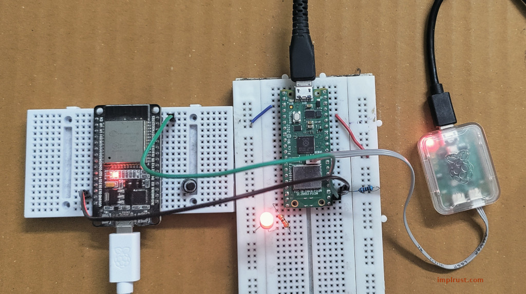
Why connect two microcontrollers?
Before You Begin
What is UART?
What We Are Going to Build
Rust from the ESP32 to the Raspberry Pi Pico when we press a button. The text is sent byte by byte over UART.Rust. If it does, the Pico will toggle the LED. It will turn the LED on if it is off, and turn it off if it is already on. Circuit
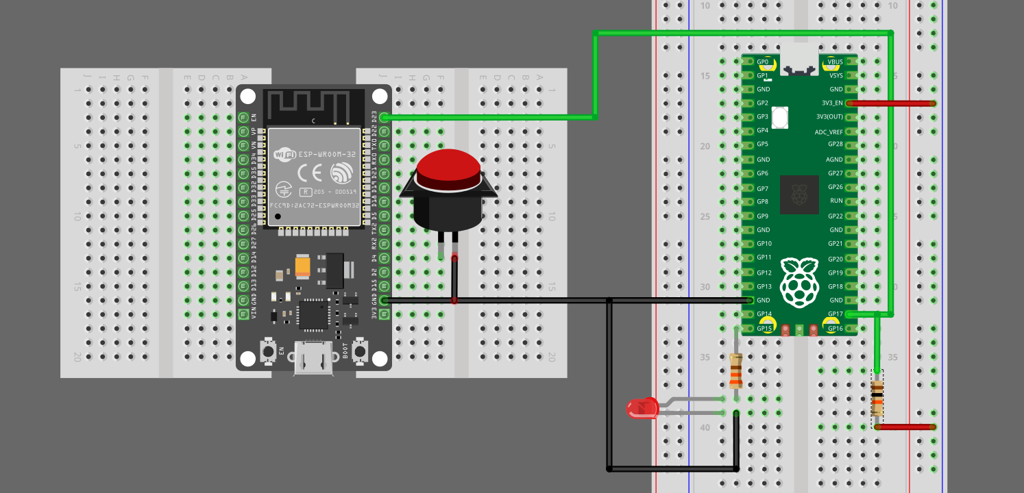
Connecting ESP32 and Raspberry Pi Pico
From Wire To ESP32 GPIO23 (TX) Pico GPIO17 (RX) Pico GPIO17 (RX) 10 kΩ resistor Pico 3.3V(OUT) ESP32 GND Pico GND Push Button
From Wire To ESP32 GPIO4 Push Button Push Button GND LED
From Wire To Pico GPIO15 330 Ω resistor LED LED GND ESP32 Code
esp-generate command. We will use the non-Embassy version for the ESP32. I will not explain the basic boilerplate code here. Instead, we will look at the parts that are relevant to our UART example.let btn = Input::new(
peripherals.GPIO4,
InputConfig::default().with_pull(Pull::Up),
);let uart_config = UartConfig::default().with_baudrate(115_200);
let mut uart = Uart::new(peripherals.UART1, uart_config)
.expect("Failed to initialize UART")
.with_tx(peripherals.GPIO23);
info!("UART is initialized");Rust followed by a newline character to the UART. We then flush the UART transmit buffer.let mut btn_pressed = false;
loop {
if btn.is_low() {
btn_pressed = true;
info!("Sending signal");
if let Err(e) = uart.write(b"Rust\n") {
error!("UART write failed: {:?}", e);
}
if let Err(e) = uart.flush() {
error!("UART flush failed: {:?}", e);
}
let delay_start = Instant::now();
while delay_start.elapsed() < Duration::from_millis(500) {}
} else if btn_pressed {
btn_pressed = false;
info!("Waiting for button press");
}
let delay_start = Instant::now();
while delay_start.elapsed() < Duration::from_millis(100) {}
}btn_pressed variable. I added it so that we can print “Waiting for button press” when the button is released. Raspberry Pi Pico Code
main function, let’s define an Embassy task called reader which will accept a UART receiver and an LED output as arguments.#[embassy_executor::task]
async fn reader(mut rx: BufferedUartRx, mut led: Output<'static>) {
info!("Reading...");
let mut buf = [0u8; 1];
let mut line: heapless::Vec<u8, 4> = heapless::Vec::new();
loop {
match rx.read(&mut buf).await {
Ok(_) => {
if buf[0] == b'\n' {
if line.eq(b"Rust") {
info!("Got Rust! Toggling...");
led.toggle();
}
line.clear();
} else if line.push(buf[0]).is_err() {
line.clear();
}
}
Err(err) => {
error!("error : {}", err);
line.clear();
}
}
}
}
line. The rx.read(&mut buf) function reads data into the specified buffer, and here we use a one-byte buffer. We keep adding the received bytes to line until we get the newline character (\n). If the contents of line match Rust, we toggle the LED and clear the vector so we can receive the next message.read function, or use other functions such as read_exact.bind_interrupts!(struct Irqs {
UART0_IRQ => BufferedInterruptHandler<UART0>;
});static RX_BUF: StaticCell<[u8; 64]> = StaticCell::new();let config = UartConfig::default();
debug_assert_eq!(config.baudrate, 115_200);
let rx_buf = &mut RX_BUF.init([0; 64])[..];
let uart_rx = BufferedUartRx::new(p.UART0, Irqs, p.PIN_17, rx_buf, config);let led = Output::new(p.PIN_15, Level::Low);reader task:unwrap!(spawner.spawn(reader(uart_rx, led)));
loop {
Timer::after_secs(1).await;
}reader task will now wait for incoming data from the ESP32 and process it as it arrives. Running the Project
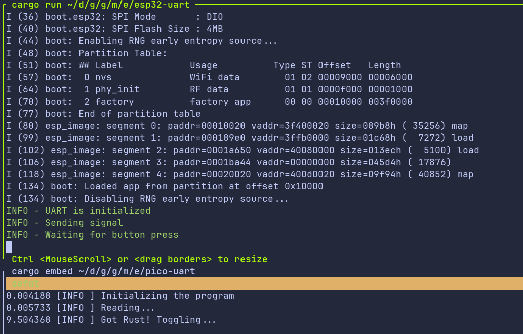
defmt or another logging option, you can also see the messages in the system console. Otherwise, you can simply observe the LED on the Pico.