Blinking an LED on STM32 Blue Pill (STM32F103C8T6) with Embedded Rust
Learn how to blink the onboard LED on the STM32 Blue Pill (STM32F103C8T6) using Embedded Rust and the stm32f1xx-hal crate. We also introduce GPIO, the PAC and HAL, and the basics of controlling digital outputs. The STM32 Blue Pill is the newest addition to my embedded hardware collection. I picked one up while ordering some other electronic components because it was so inexpensive. The Blue Pill is a low-cost development board based on the STM32F103C8T6 microcontroller, often abbreviated as STM32F103C8, from STMicroelectronics. The STM32F103 microcontroller was first introduced in 2007. It is based on a 32-bit Arm Cortex-M3 processor and provides 64 KB of Flash memory and 20 KB of SRAM. If you are buying a development board today, you may want to consider a newer option with better performance and more features. There are plenty of tutorials for the Blue Pill using C and other programming languages. In this post, however, i’ll use Embedded Rust. I am planning to start with a simple LED blinky program using this board. I might turn it into a series as I explore more of what the STM32 Blue Pill has to offer. This tutorial assumes you are familiar with basic Rust programming and fundamental electronics concepts. It also assumes you already have an Embedded Rust development environment set up. If not, I recommend reading the following guide first: Setting Up an Embedded Rust Development Environment In order to run our program, we need a way to transfer it from our computer to the STM32F103C8T6 microcontroller. Unlike some development boards, we cannot directly flash a Rust program to the Blue Pill by simply connecting a USB cable. Instead, we need a “hardware debugger and programmer” that communicates with the microcontroller through the Serial Wire Debug (SWD) interface. In this tutorial, I will be using an ST-LINK V2 Debugger & Programmer. It is cheap, widely available, and works well for programming and debugging STM32 microcontrollers. Besides SWD, there are other ways to program the Blue Pill. However, I have not tried them, so we will use an SWD debugger throughout this tutorial. Connect the Blue Pill development board to the ST-LINK V2 using a few jumper wires, as shown below: The ST-LINK V2 will provide power to the Blue Pill through the 3.3V connection, so you do not need to connect a separate USB cable to the development board. GPIO stands for General Purpose Input/Output, which are pins that allow a microcontroller to communicate with the outside world. The STM32F103C8T6 microcontroller provides several GPIO pins that can be configured as either inputs or outputs. The Blue Pill development board includes an onboard LED connected to pin For example: Embedded Rust is built on a collection of crates that work together to provide access to microcontroller hardware. Our project uses several crates, each with a specific purpose. The most important one is Embedded Rust projects typically use two crates: I will not be creating the project from scratch. That would require configuring many files and settings, which requires a separate post on its own. To keep things simple and get started quickly, we will use an existing project template. The Cargo Generate will ask you a few questions. For this tutorial, use the following answers: Once the template finishes generating, you will have a new Embedded Rust project. The directory structure should look similar to this: Don’t worry about the other files for now. We will focus only on the Open the This looks quite different from a project we would normally create with Regular Rust applications use the standard library ( Microcontrollers like the STM32F103C8T6 do not run an operating system, so Embedded Rust programs use the The The template also includes the following line: A panic occurs when a program encounters an unrecoverable error. The Now, replace the You know what? Before understanding the code, let’s go ahead and flash the program onto the Blue Pill to see it in action. If you get stuck or want to compare your code, you can use the complete project from my GitHub repository: Now, let’s go back and understand what each line of the program does. The first line inside the The Notice that we call The Embedded Rust ecosystem leverages Rust’s ownership system to enforce this singleton pattern. This ensures that only one part of the program can own and control each peripheral at a time, helping avoid conflicting configurations and other unpredictable behavior. The next line is: The The next line is: Just like Next, we configure pin The Finally, we repeatedly turn the LED on and off: The This is because the LED is connected in an active-low configuration. An active-low signal means the device or function becomes active when the signal is LOW (logic The Congratulations! You have written and flashed your first Embedded Rust program on the STM32 Blue Pill. Once you are comfortable with this example, I encourage you to explore the examples included with the As you work through them, try to understand what each example is doing instead of simply running it. This is one of the best ways to become familiar with the STM32F103C8T6 and Embedded Rust.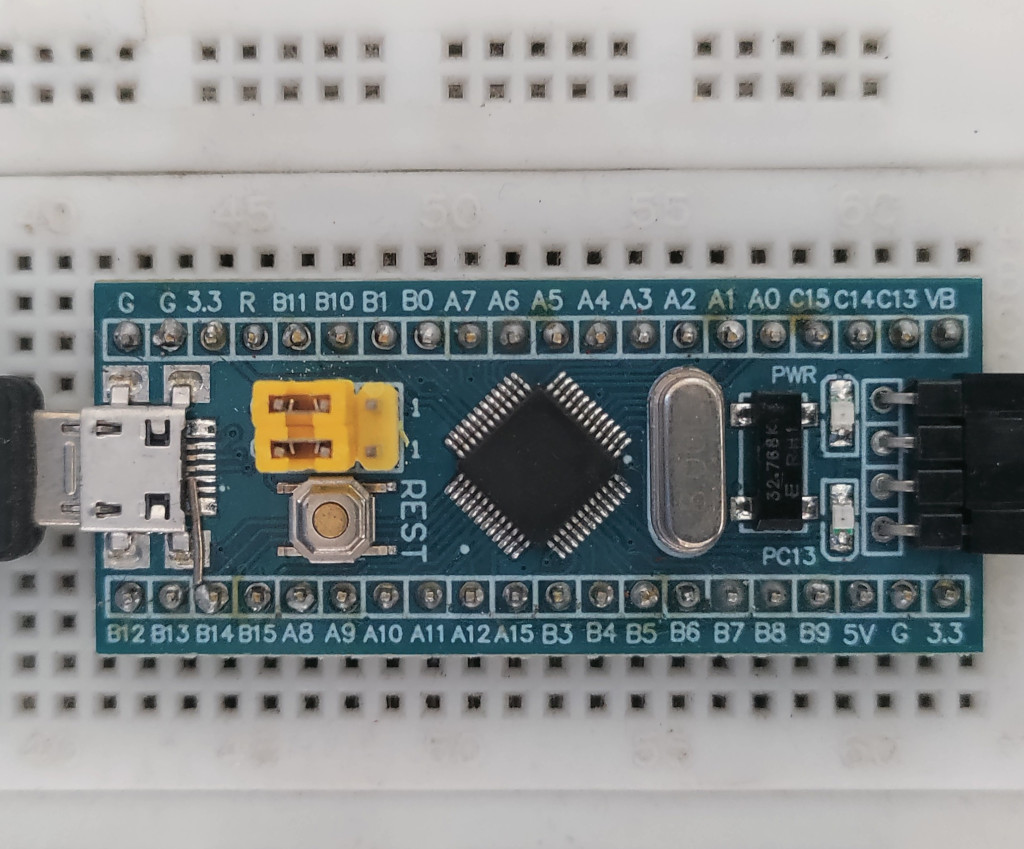
Before You Begin
Hardware Debugger & Programmer
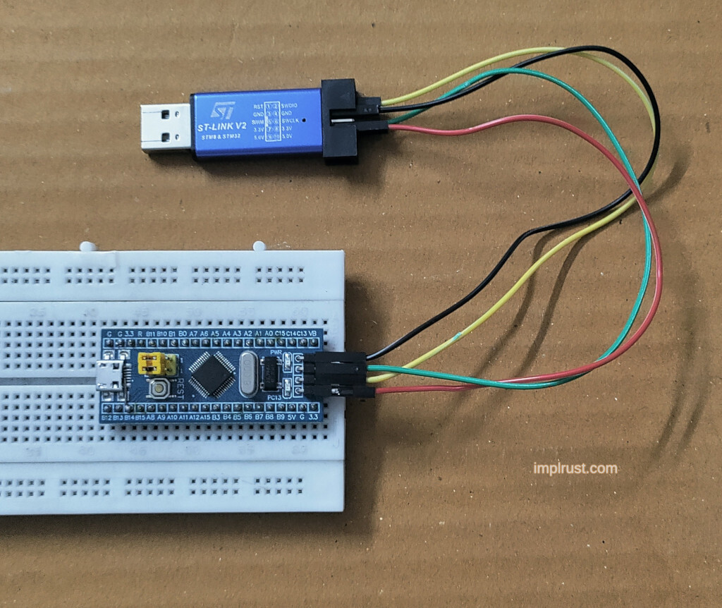
Connecting the Blue Pill to the ST-LINK V2
Blue Pill ST-LINK V2 3.3V 3.3V SWDIO SWDIO SWCLK SWCLK GND GND The Onboard LED and GPIO Pins
PC13. If you are new to STM32 microcontrollers, the name PC13 might look a little confusing. STM32 microcontrollers organize GPIO pins into ports, identified by letters such as A, B, and C. Each port contains multiple numbered pins.PA0 means Port A, Pin 0.PB5 means Port B, Pin 5.PC13 means Port C, Pin 13. Embedded Rust Ecosystem
stm32f1xx-hal, a Hardware Abstraction Layer (HAL) that provides a safe and convenient API for working with peripherals such as GPIO pins, timers, UART, SPI, and I2C. Creating the Project
stm32f1xx-hal repository links to the following project template, so we’ll also use it in this tutorial:cargo generate --git https://github.com/burrbull/stm32-template.gitProject Name: hello-blinky
What microcontroller name?: stm32f103c8t6
What HAL version to use?: last-release
Is it RTIC-based application?: false
Will this program use defmt logger?: true
Do you want to load SVD and add it to VSCode task?: falsestm32f103c8t6.stm32f1xx-hal.false.defmt logging framework. This provides an efficient way to print debug messages from embedded programs. We will use it throughout this series, so select true.false..
├── build.rs
├── Cargo.toml
├── Embed.toml
├── memory.x
├── README.md
└── src
└── main.rsmain.rs file. Generated Boilerplate
src/main.rs file. The template already provides a minimal Embedded Rust program that looks like this:#![deny(unsafe_code)]
#![no_main]
#![no_std]
// Print panic message to probe console
use panic_probe as _;
use cortex_m_rt::entry;
use stm32f1xx_hal::{
pac,
prelude::*,
};
#[allow(clippy::empty_loop)]
#[entry]
fn main() -> ! {
loop {}
}cargo new. That’s because embedded systems have different requirements than desktop applications, so the template includes a few additional attributes and crates.
#![no_std]std), which provides features such as file handling, networking, and threads. These features depend on an operating system.core library instead. The #![no_std] attribute tells the compiler not to link the standard library.
#![no_main]#![no_main] attribute tells the compiler not to use the normal Rust program entry point. Instead, the program starts from an entry point provided by the embedded runtime.
panic_probeuse panic_probe as _;panic_probe crate reports panic messages through the debug probe, making them useful for debugging. Modifying the main Function
main function with the following code:fn main() -> ! {
let p = pac::Peripherals::take().unwrap();
let mut rcc = p.RCC.constrain();
let mut gpioc = p.GPIOC.split(&mut rcc);
let mut led = gpioc.pc13.into_push_pull_output(&mut gpioc.crh);
loop {
    led.set_low();
    cortex_m::asm::delay(5_000_000);

    led.set_high();
    cortex_m::asm::delay(5_000_000);
}
}cargo run --releasegit clone https://github.com/ImplFerris/stm32f103c8t6-projects.git
cd stm32f103c8t6-projects/stm32f1xx-hal/blinky
cargo run --release Accessing the Peripherals
main function is:let p = pac::Peripherals::take().unwrap();pac module provides access to the hardware peripherals of the STM32F103C8T6 microcontroller, such as GPIO.Peripherals::take() instead of creating a new Peripherals object. There is only one set of hardware peripherals inside the microcontroller, so take() can only be called once, giving our program exclusive ownership of them. Reset and Clock Control (RCC)
let mut rcc = p.RCC.constrain();RCC stands for Reset and Clock Control. It is responsible for managing the clocks and reset behavior of the microcontroller’s peripherals.RCC value returned by the Peripheral Access Crate (PAC) provides direct access to the hardware registers. Calling constrain() converts it into the HAL’s Rcc type, providing a safer and more convenient interface to work with. We will use this rcc value in the next line when configuring the GPIO peripheral. Splitting the GPIO Peripheral
let mut gpioc = p.GPIOC.split(&mut rcc);RCC, GPIOC is initially provided by the PAC. Calling split() converts it into a higher-level HAL interface. The split() method also enables the clock for the GPIOC peripheral and returns an object that provides access to the individual GPIO pins. Configuring
PC13 as an OutputPC13 as an output:let mut led = gpioc.pc13.into_push_pull_output(&mut gpioc.crh);into_push_pull_output() method configures pin PC13 as a digital output so that our program can control the onboard LED. Blinking the LED
loop {
led.set_low();
cortex_m::asm::delay(5_000_000);
led.set_high();
cortex_m::asm::delay(5_000_000);
}set_low() and set_high() methods change the state of the PC13 pin. On the Blue Pill development board, set_low() turns the onboard LED on, while set_high() turns it off.0) instead of HIGH (logic 1). In our case, driving PC13 LOW turns the LED on, while driving it HIGH turns the LED off.delay() function simply waits for a short period before changing the LED state again, making the blinking visible. What’s Next
stm32f1xx-hal project. They cover many peripherals and features.