Analyzing UART Signals in Embedded Rust Using a Cheap USB Logic Analyzer
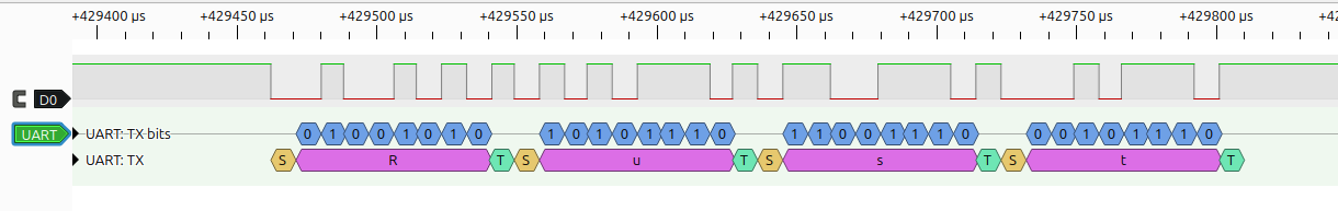
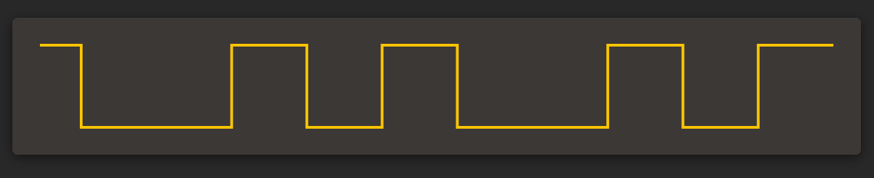
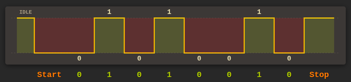
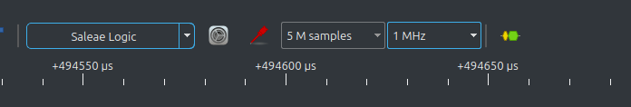
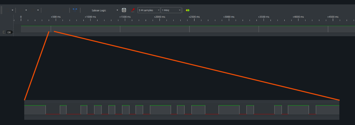
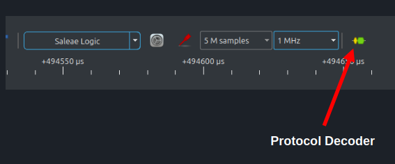
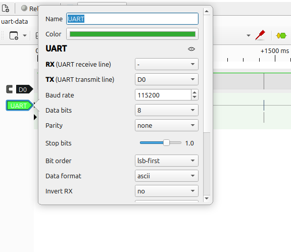
In this post, we analyze UART signals from an embedded Rust project using a cheap USB logic analyzer and PulseView. We capture UART data, look at the raw signal on the wire, and use protocol decoding to understand how bytes are transmitted. In my previous blog post, I introduced the USB logic analyzer, showed how to set up the software, and used a simple GPIO toggle to get familiar with how a logic analyzer works. In this post, we look at UART and see how serial data appears on the wire by analyzing the transmit (TX) signal and understanding how bytes are sent. I initially planned to explain I2C right after the introduction, but I felt that UART is much simpler to start with and provides a gentler introduction to using protocol decoders in PulseView. You might already be familiar with UART. Still, let me give a short introduction. UART stands for Universal Asynchronous Receiver-Transmitter. It is a simple serial communication method used to send data between two devices. Data is sent one bit at a time, rather than in parallel. UART typically uses two signal lines: one for transmitting data (TX) and one for receiving data (RX). The TX pin of one device is connected to the RX pin of the other, so data sent on TX is received on RX. Unlike some other protocols, UART does not use a clock signal. So a natural question is how the receiver knows when data starts, when it ends, and how to interpret the bits correctly. Let us look at a simple UART signal to understand this. We can assign LOW state to 0 and HIGH to 1, but this alone is not enough. For example, suppose we want to transmit the value 0x52 (binary 0101_0010). If two or more bits in a row have the same value, such as two consecutive zeros, how does the receiver know whether it is seeing one long zero or multiple zeros? This is where three important UART things come into play: the data length, the start and stop bits, and the transmission speed (baud rate). These three define how many bits make up a byte, and how the beginning and end of a byte are identified, how fast the data is sent. The baud rate defines how fast bits are transmitted on the wire. It specifies how many bits are sent per second. For example, a baud rate of 115200 means that 115200 bits are transmitted every second. Both the transmitter and receiver must use the same baud rate. If the baud rate does not match, the receiver will sample the signal at the wrong times and decode incorrect data. The data length specifies how many data bits are sent for each character. The most common configuration is 8 data bits, but other values like 5 to 9 bits are also possible. If the data length is set to 8 bits, then exactly 8 data bits are transmitted for each byte, one after another, starting with the least significant bit. When the UART line is idle, it stays in the HIGH state. A transmission always begins with a start bit, which is a transition from HIGH to LOW. This LOW level tells the receiver that a new byte is starting. Once the receiver detects the start bit, it uses the baud rate to time when to read the following data bits. After all data bits are transmitted, the sender adds one or more stop bits. A stop bit is simply the line returning to the HIGH state for a fixed duration. The stop bit marks the end of the byte and gives the receiver time to finish processing the current byte before the next one begins. The above diagram shows the transmission of a single UART data byte. Before any data is sent, the signal stays in the idle state, which is HIGH. The transmission begins with the start bit. The start bit is represented by pulling the signal LOW for exactly one bit duration. This transition from HIGH to LOW tells the receiver that a new byte is about to start. Immediately after the start bit, the actual data bits are transmitted. In this example, the byte being sent is 0x52, which in binary is 0101_0010. UART sends data least significant bit first, so the first data bit sent is 0. Because the start bit is LOW and the first data bit is also 0, the signal stays LOW for two consecutive bit periods. From the waveform alone, these two consecutive LOW levels appear as one continuous LOW signal. The receiver does not get confused because it does not rely on signal edges to count bits. Instead, it relies on timing. This is where the baud rate comes in. The baud rate defines how long one bit lasts. For example, at a baud rate of 115200, each bit lasts for about 8.68 microseconds. The receiver measures time from the start bit and samples the signal at fixed intervals, once per bit period. By sampling at these precise times, it knows when one bit ends and the next bit begins, even if the signal level does not change. After all data bits are transmitted, the signal returns to HIGH for the stop bit. The stop bit marks the end of the byte and brings the line back to the idle state. If another byte is sent, the process repeats with another start bit. As long as both sides agree on the baud rate and data format, the receiver can correctly interpret a continuous stream of HIGH and LOW levels as individual bits and bytes. I intentionally avoided many details of UART in this post. I only covered what is necessary for our purpose here and skipped other topics such as parity bits and other. If you want to go deeper, I recommend reading more about UART separately. For this post, I am focusing only on the transmit (TX) pin. The receive (RX) pin works in the same way, just in the opposite direction. Once again, I am using a Raspberry Pi Pico. I will use one of the UART TX pins available on the Pico. In this example, I am using GPIO16 as the UART TX pin. You are free to use a different UART TX pin if you prefer, but you will need to adjust the code accordingly. Connect CH1 of the logic analyzer to GPIO16 on the Pico. Also connect the logic analyzer ground to any ground pin on the Pico. Flash the program onto the Pico, then power up the board and connect the USB logic analyzer to the computer. In our example, the UART baud rate is 115200. To capture the signal reliably, we use a sample rate of 1 MHz, which is comfortably higher than the baud rate and works well with PulseView. The program sends the string “Rust” once every second and then stays idle in between. Because of this, the capture window must be long enough to include at least one transmission. Using 5 million samples at a 1 MHz sample rate gives a capture duration of about 5 seconds. This ensures that several UART transmissions are captured without having to worry about timing the capture manually. Since the program transmits the text “Rust” once every second, the capture contains multiple UART transmissions spread across the entire capture window. Because we are viewing several seconds of data at once, the waveform is zoomed out by default. At first glance, it might look like nothing happened. The signal appears mostly flat, with a few thin vertical-looking shapes. These vertical shapes are not single lines. Each one represents a short burst of UART activity where the “Rust” string was transmitted. To see what is actually happening, zoom in horizontally on one of these regions (you can use the mouse scroll wheel while the cursor is over the signal). Once you zoom in far enough , the individual signal transitions become visible. At this level, you can see the structure of each UART transmission, but not the meaning of individual bits. To make sense of the data, we will use the protocol decoder feature. Looking at the raw UART signal helps confirm that data is being transmitted, but it does not tell us what the data actually is. PulseView provides protocol decoders for many common digital protocols such as UART, I2C, and SPI. These decoders interpret raw signals and display the data in a readable form. To add a protocol decoder, click the small decoder icon next to the “sample rate” selection, as highlighted in the image above. This opens the Decoder selector. In the search box, type After adding it, you will see a message saying that no channels are assigned to the decoder. At this point, PulseView knows which protocol to use, but it does not yet know which signal line to decode. Click on the UART label on the left side to open the decoder settings. Here, we need to configure the decoder to match our UART setup. Set the baud rate to 115200. The default values for data bits, parity, and stop bits are fine for this example. By default, the decoded data format is shown in hexadecimal. Since we are transmitting ASCII text, change the data format to ASCII. Finally, assign the signal channel to the decoder. We have connected the UART TX pin to CH1, which corresponds to D0 in PulseView. Select D0 from the dropdown next to the TX option. Once this is done, PulseView will decode the captured UART signal and display the transmitted data. PulseView decodes the captured UART signal and displays the data in a readable form. Along with the decoded characters (in ASCII, as we configured), it also shows the individual data bits as 0 and 1. PulseView also highlights the start bit with an “S” label (shown in yellow) and the stop bit with a “T” label. What is UART?
Baud Rate (Transmission Speed)
Data Length
Start and Stop Bits
Example
Hardware Setup
Logic Analyzer Raspberry Pi Pico GND GND CH1 GPIO16 Code Snippet
async
Number of Samples and Sample Rate
Start the Capture
Protocol Decoder
UART and double-click the UART decoder. This adds a new UART decoder row to the main window.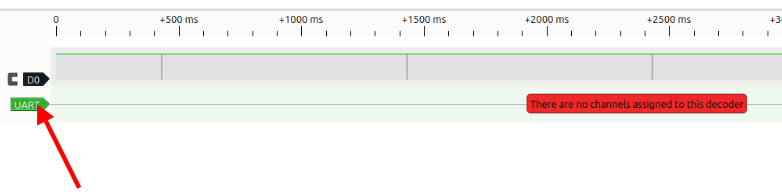
Decoded Data